Two Products. One Intelligence Platform.
From planning optimal routes to proving equipment value, we turn field operations into structured, actionable intelligence.
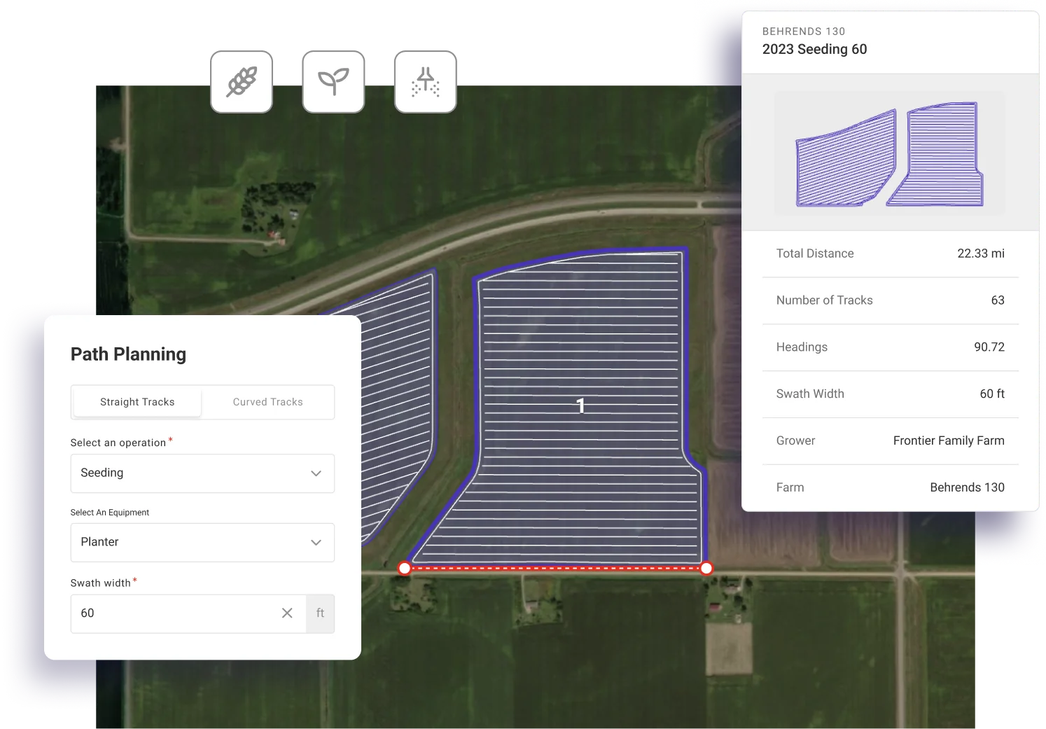
Path Planner
The intelligence layer for autonomous farming. Create optimized field routes that capture grower intent, minimize soil loss, reduce overlap, and enable supervised autonomy today.
AI-powered field analysis and boundary detection
3D terrain modeling to minimize soil erosion
Complete route generation with turns and connectors
Export to all major equipment brands
Equipment Explorer
Prove equipment value on real fields. Compare working widths, GPS accuracy, and section control with field-specific productivity calculations that close deals.
Calculate effective field productivity vs theoretical
Quantify GPS accuracy upgrade ROI
Compare section control configurations
Win deals with field-specific data