Overview
Our state-of-the-art routing solution supports arbitrarily complex fields, headland navigation, and many other configurable options. On this page you'll find examples + explanations of the various routing features, as well as new and exciting experimental prototypes.
Turn Modelling
We support various turn types, which are chosen automatically depending on a combination of field geometry and equipment characteristics. If two tracks are within 3 swath widths of each other, we will attempt to directly connect them with a turn. If the turns are farther apart, or there is no turn that can fit, we instead will perform what we call a headland traversal, explained in more detail below.
Track-Track Connectors
If making a direct connection from a track to track, we support the following types of turns:
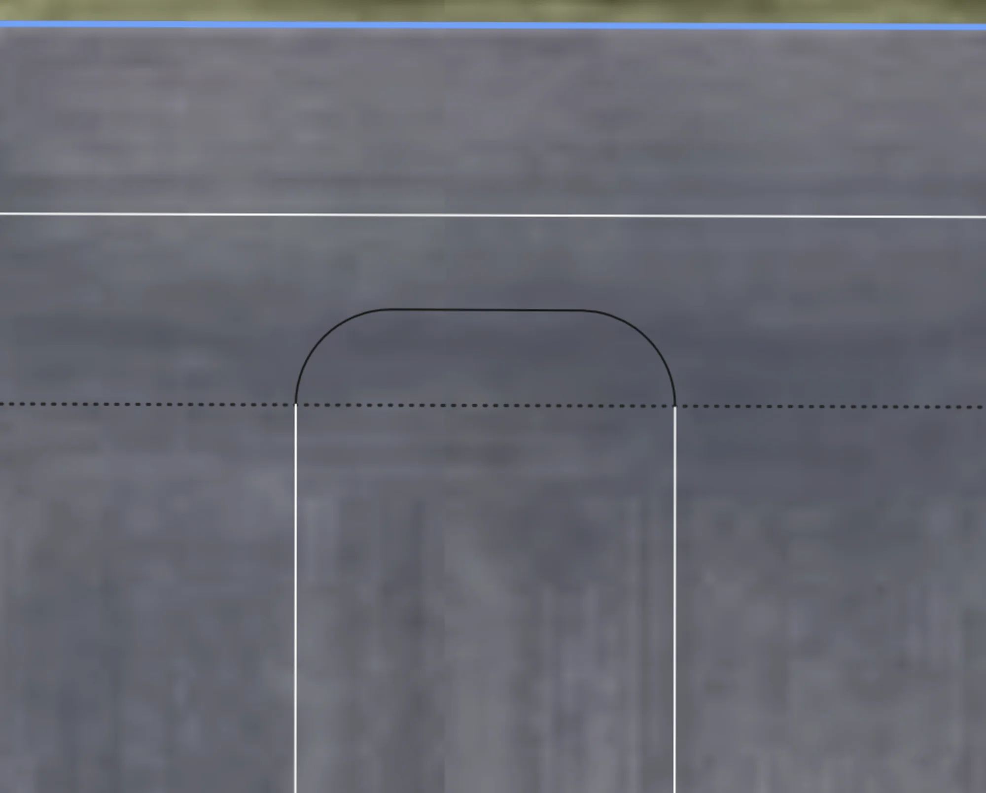
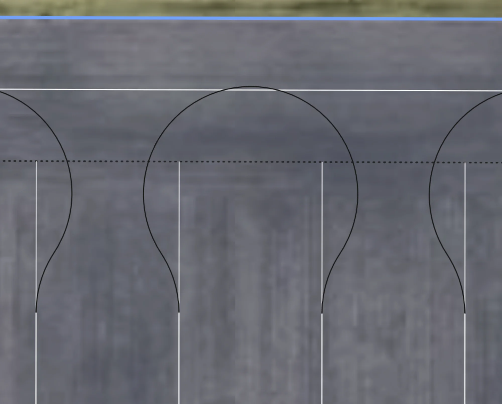
U-Turn
When turn radius is less than 50% of the swath width, U-turns such as this will be generated for adjacent tracks. Note there is an option to extend the straight segment to the headland to give more room to turn and to minimize trampling.
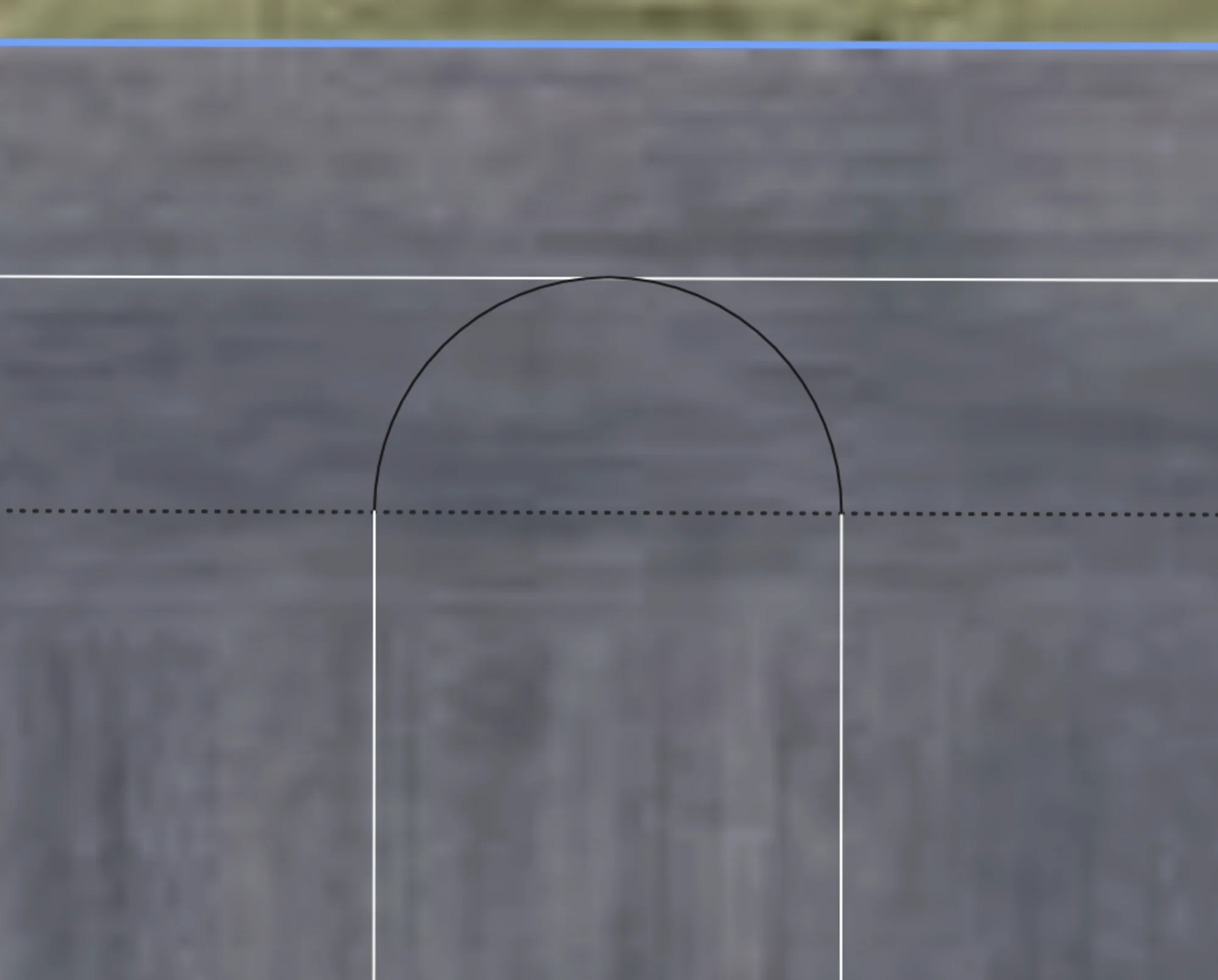
Perfect U-Turn
When turn radius is exactly 50% of the swath width, Perfect U-turns such as this will be generated for adjacent tracks, with no straight segment inbetween.
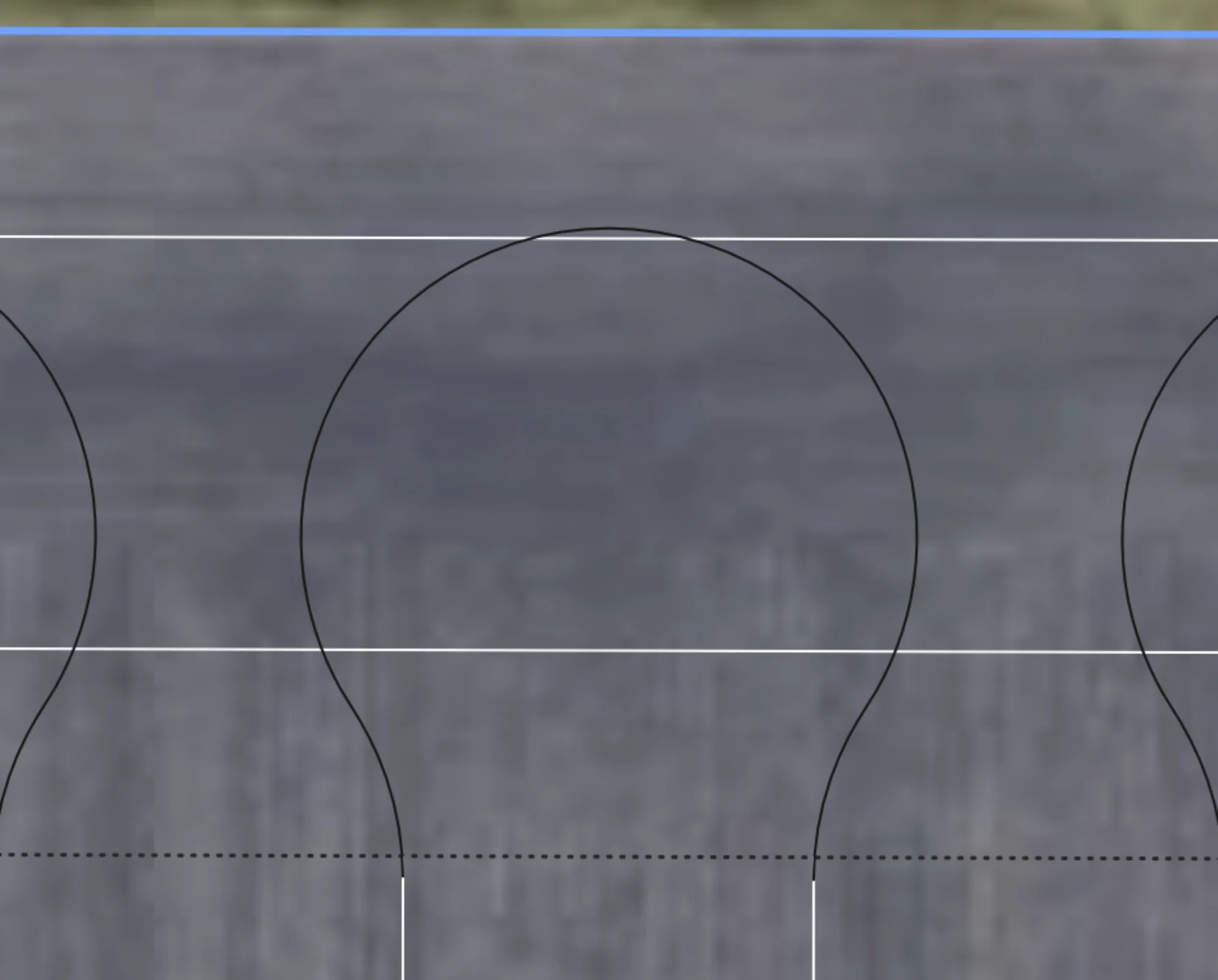
Bulb Turn
When turn radius is greater than 50% of swath width, a bulb turn is used to connect two adjacent tracks. This would only be used if a U-turn could not fit.
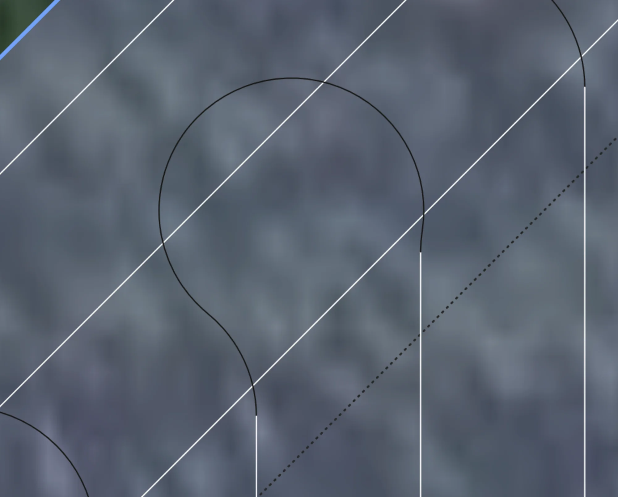
P Turn
If the headland is at a sharp angle compared to the turn, and the turn radius is large enough, we support P turns to minimize the amount of steering required to make the turn.
Track-Headland Connectors
If a direct connection can't be made, we will instead connect onto a nearby headland, performing one or more headland traversals to connect two tracks. This allows us to create paths between almost any two tracks in the entire field without invalidly crossing the field outside of a headland zone.
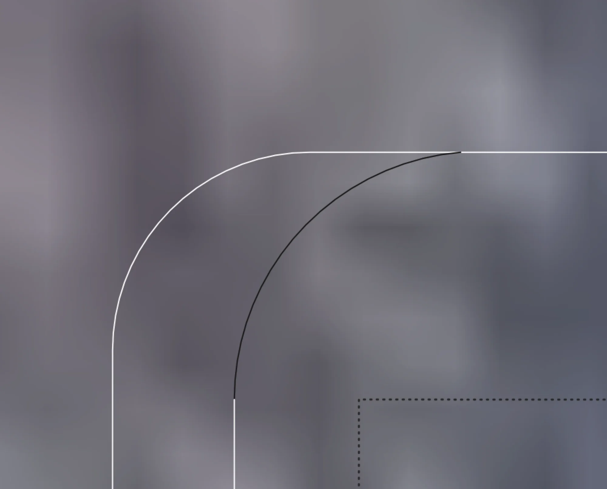
Arc Connectors
By default, we try to use arc connectors, which have constant curvature and have a turn radius at least as large as minimum turning radius. This allows for a smooth transition from the track to the headland without any jerky motions. Turn may be automatically shortened if there is not enough room to complete the turn without the vehicle leaving the boundary.
Dubins Connectors
If an arc connector fails, a search is performed to try to connect a dubins connector onto various points on the headland in the desired direction of travel, until a valid one is found that minimizes total angle change.
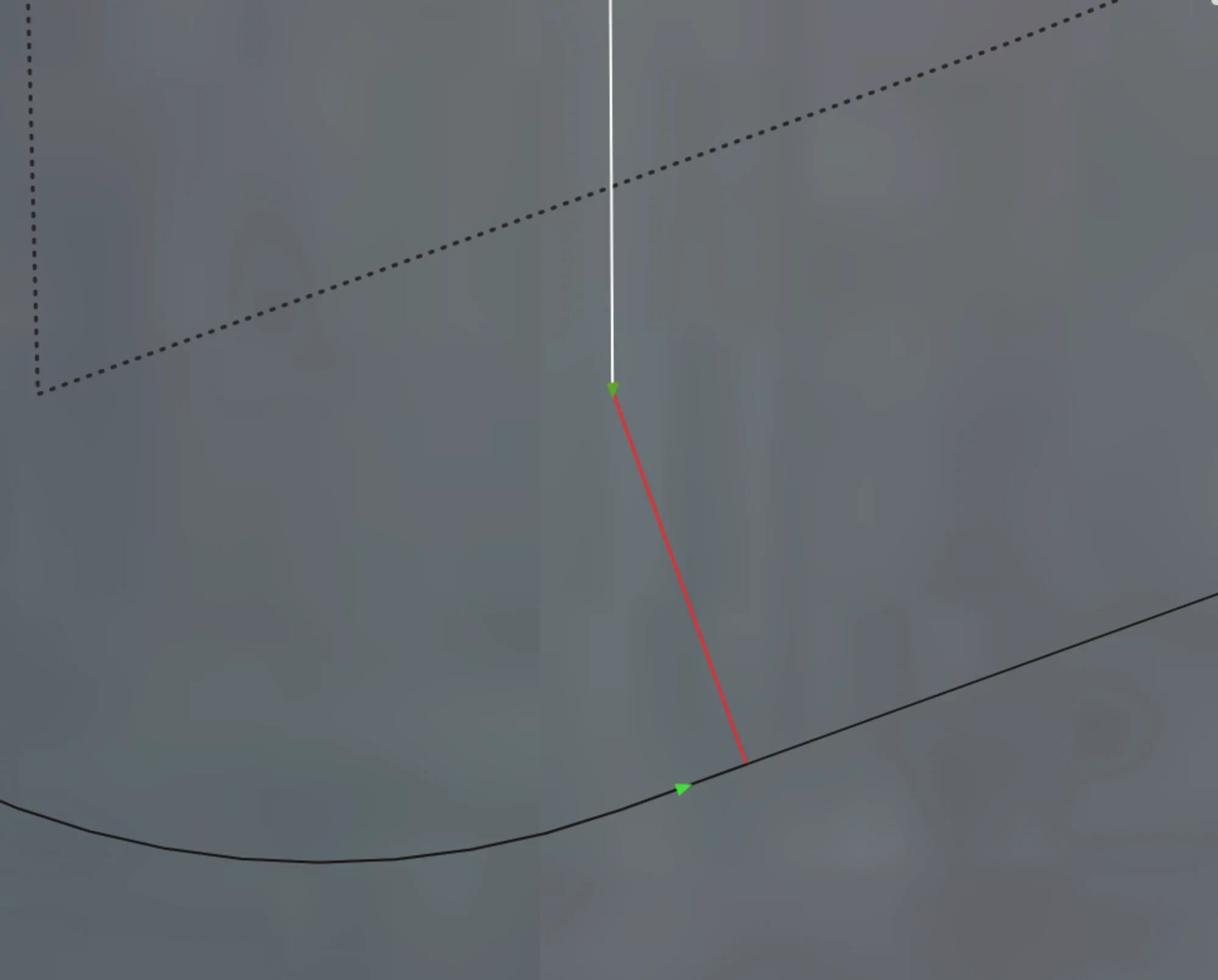
Fallback Connector
If all else fails, we create a fallback connector, which just directly joins the two points (either between two tracks or track-headland) and shows up in the UI as a big red line. User must manually make this turn before continuing the route.
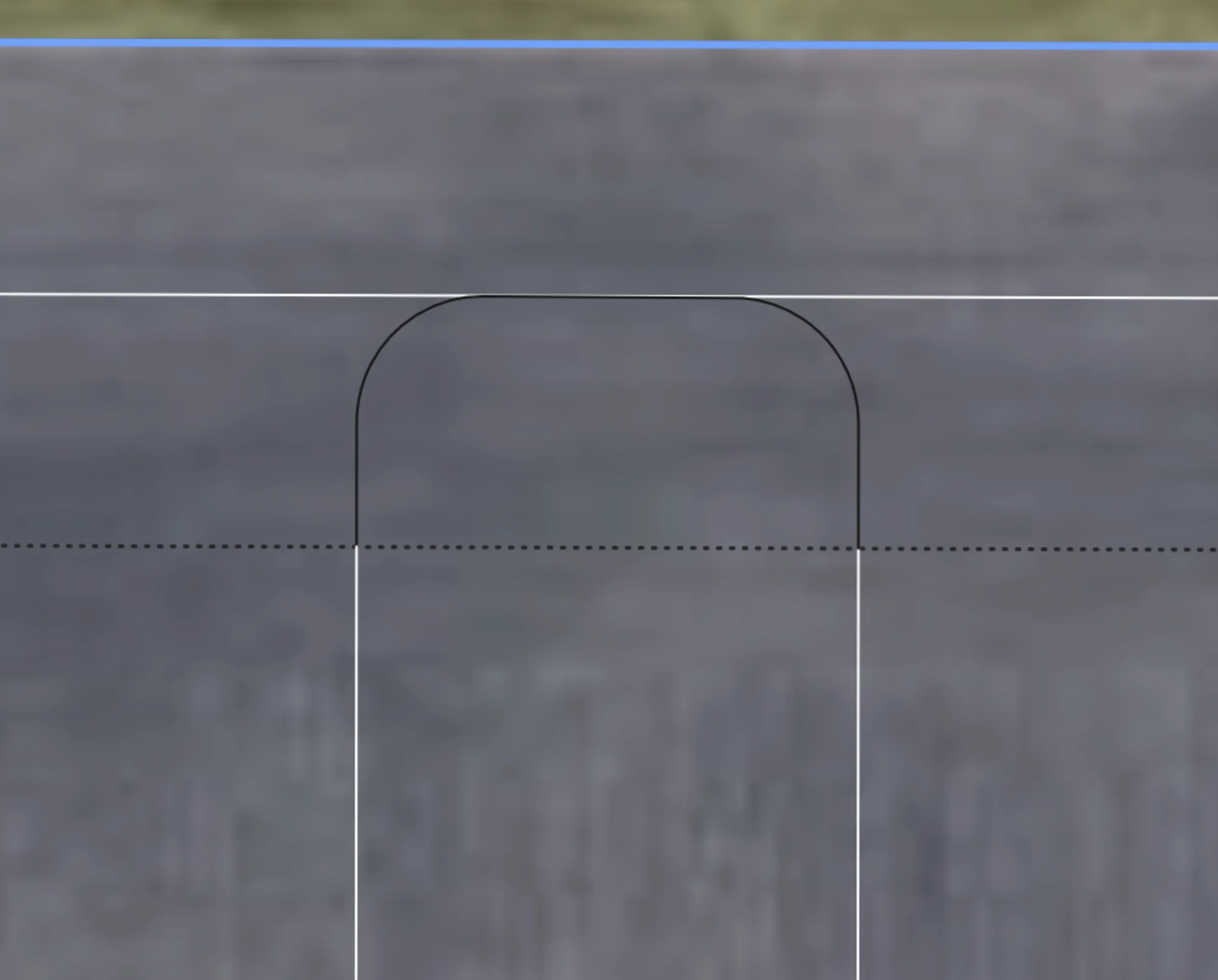
Turn Shortening
If a turn can't fit from a track to another track or to a headland without any part of the vehicle leaving the boundary, and if the "Shorten Tracks" setting is enabled, the turn will be shortened, i.e turn sooner than the end of the track so that it can make it. Unfortunately this causes a miss, unless your vehicle can reverse before making the turn (future work would support this functionality if there is desire for it). If you notice that a lot of area is being missed, you likely don't have enough headlands based on your vehicle's turn radius, and may need to rerun the plan with more headlands. On the roadmap is to automatically suggest # of headlands based on your field and equipment.
Turn Extending
In some situations, you may wish to actually extend your turns into the headland further. This can be enabled by toggling the "Extend Turns Into Headlands" setting. If a turn can fit, it will be extended so that it touches the outermost headland. This allows for more room for turning, to straighten out, and minimizes trampling. Future work includes always latching onto headlands when possible to even further minimize trampling.
Shortened Headland Connections
Adjacent turns that are shortened to fit on the headland will instead be converted to headland traversals if possible. This can be enabled by toggling "Prefer Shortened Headland Connections". Future work includes enabling this for all track-track connections.
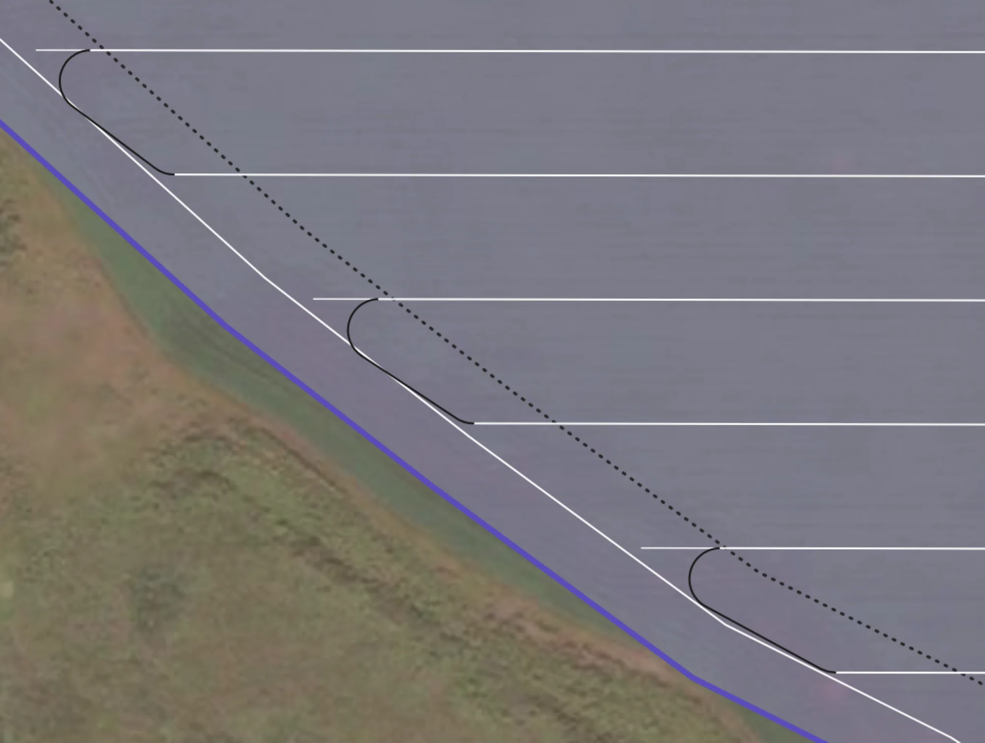
Without Setting
The turn is shortened to just touch the headland, but doesn't actually traverse along it.
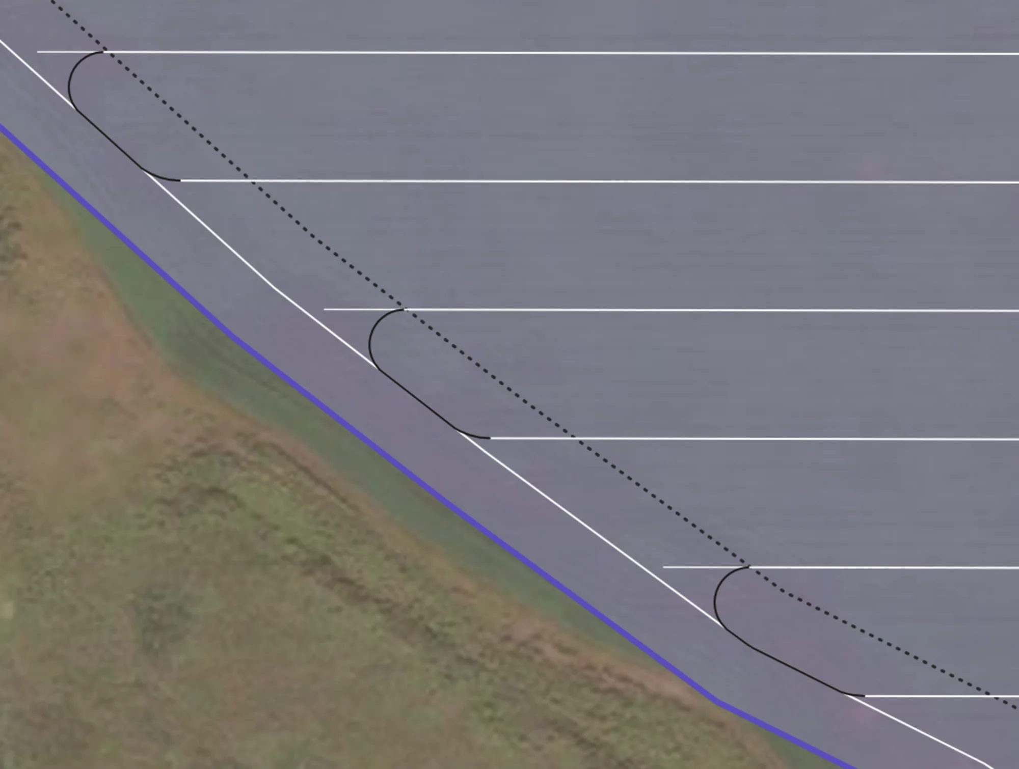
With Setting
Connections are made onto the headland between adjacent connectors, minimizing trampling.
Headland Navigation
When a direction turn from track to track isn't possible, the routing solution will instead switch over to headland navigation mode. Connectors from the tracks to the headlands will be made, followed by a series of headland traversals and connectors between headlands.
Full Headland Traversals
Automatically work all the headlands in your field with additional planning, as we efficiently find a path to and from each headland in a group, minimizing the amount of non-working distance travelled while preversing wheel traffic. Our algorithm can work from any starting or ending track on the headland. The algorithm prevents any turns that might collide with the obstacle, ensuring safety.
Out-to-In Pattern
Outermost headlands are worked first, going inwards to the closest ones.
In-to-Out Pattern
Innermost headlands are traversed to first, going outwards.
Complex Multi-hole Traversals
Multiple holes in a single 'group' being traversed. The first time the route meets a headland group, it works all of them, then all future turns use the headlands to navigate to other parts of the field. Note that there are some somewhat odd traversals, because we always force headland connections.
Traversals w/ Drivethrough
Same headland group, but now the "Enable Headland Drivethrough" setting is enabled. Note how it simplifies the traversals, reducing the amount of turning, at the cost of potentially increasing trampling. Headland drivethroughs will only ever be executed if the width of the vehicle can pass through without hitting anything.
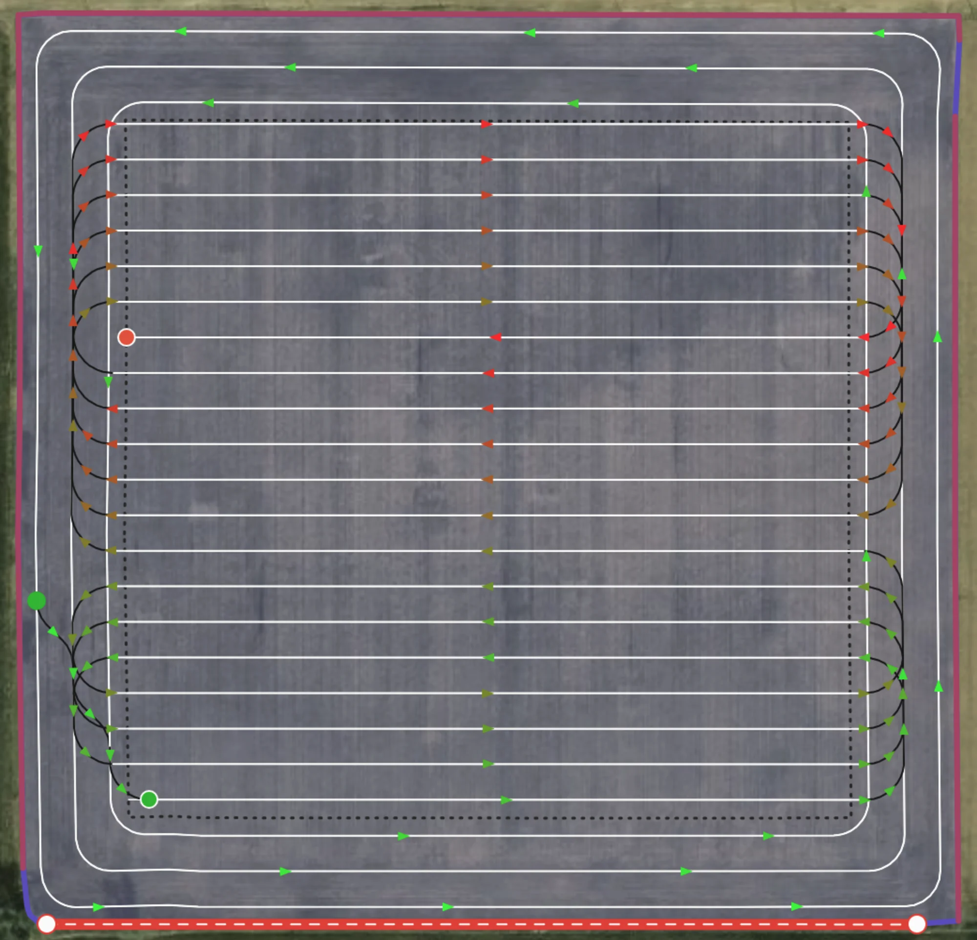
Headlands First/Last
Users can specify if they want to work the exterior headlands first or last in the route. If first, the passes will be worked out->in in a counter-clockwise direction, and if last, the passes will be worked in->out ain the same direction after all tracks. The driving direction can also be changed to clockwise.
Headlands First
Headlands worked out->in first, then tracks. Route ends on last track.
Headlands Last
Route starts at track, all tracks worked, then the headlands from in->out. Route ends on headland.
Prefer Outermost Headland
When performing headland traversals, the algorithm defaults to attaching to the middle most exterior headland, as it provides a good tradeoff between room for turning and straightening out. Enabling "Prefer Outermost Headland" will instead attach to the outermost headland.
Default behaviour
Headland traversals naturally attach to the middle most headland.
Turns Attached to Outermost Headland
When "Prefer Outermost Headland" is enabled, all headland traversals attach to the outermost exterior headland if possible.
Headland Direction
Choose which direction you want to work headlands, in either a clockwise or counter clockwise direction depending on what suits your setup better. If not specified, CCW direction is chosen by default for exterior and whichever direction is better in the situation for interior headlands. Currently not exposed via UI but available in our API.
Counter Clockwise (Winding)
CCW direction allows you to offload to ther right of your vehicle
Clockwise (Reverse Winding)
CW direction allows you to offload to ther left of your vehicle
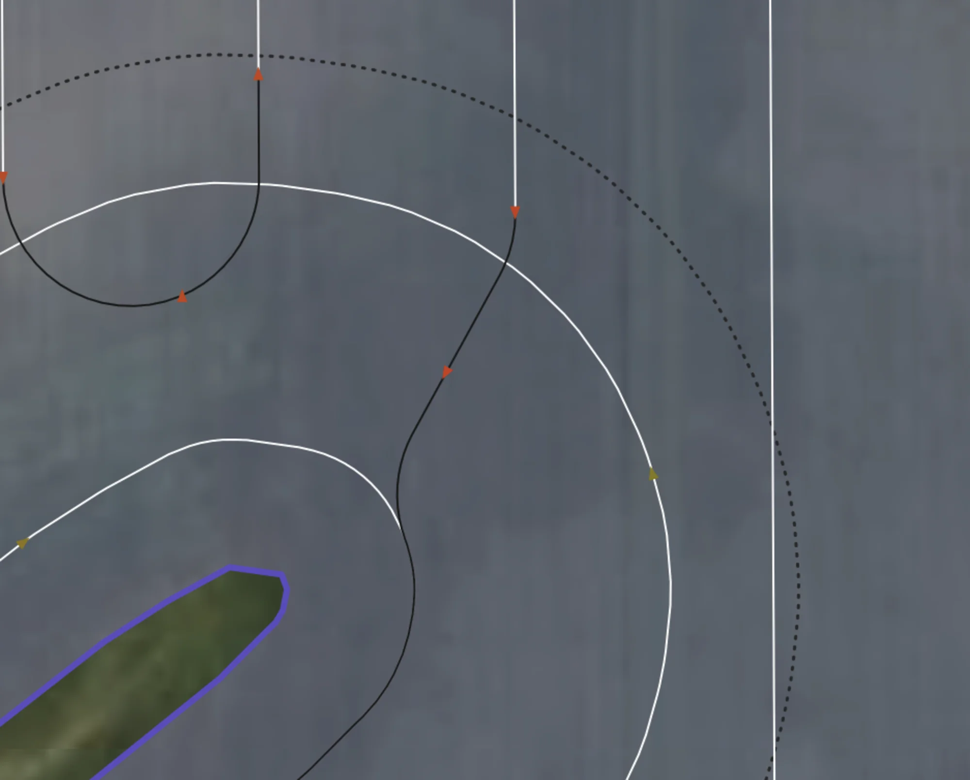
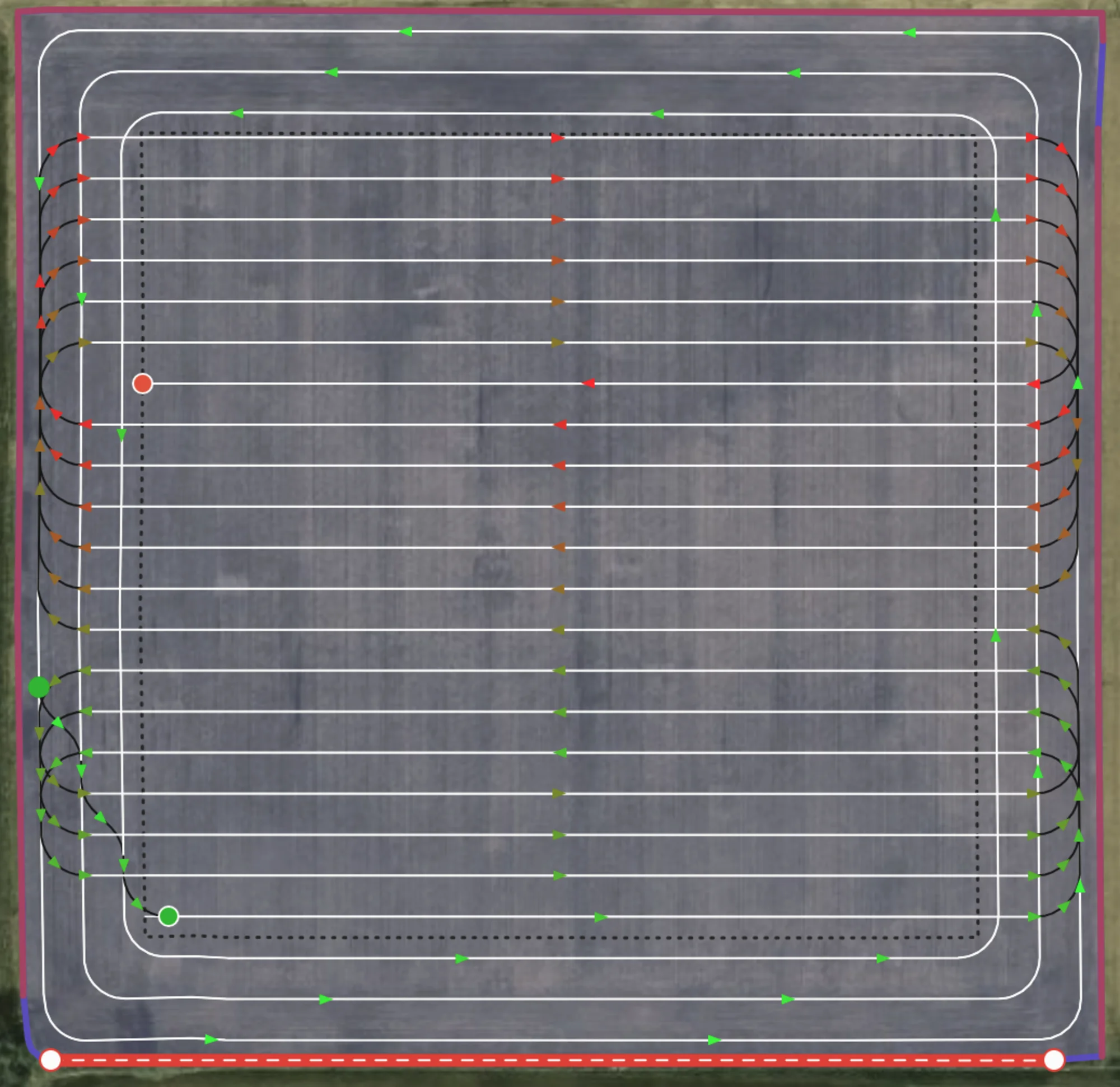
Multiple Internal Track Routing
Example of a complicated situation where the route solver finds a path through multiple headlands, working them, as well as all the internal tracks.
Algorithms / Patterns
Default Algorithm
By default, we model the problem as an instance of a Agricultural Routing Problem (ARP), which is the agricultural version of the well-known Vehicle Routing Problem. Its what's known as NP-hard, meaning there are no algorithms that can efficiently solve all possible instances of the problem perfectly. That is why we have developed a custom meta-heuristic solver to solve the ARP, encoding grower standards into the cost matrix itself, generating a route that can navigate even the most complex fields, in the matter of minutes or even seconds.
Our routing solver calculates the distances to/from every possible pair of tracks on the field, using exact routes for tracks in roughly the same area, and smart estimates for tracks on opposite side of the field. This creates what's known as a distance matrix, which is then fed into our propreitary solver to optimize a path that traverses every track and headland, while minimizing non-working distance. No prior assumptions are made about the working pattern, the results are solely based off the calculated distances between them. This allows the solver to have incredible foresight at times, skipping one or more tracks that aren't immediately obvious to a user, only to then use those tracks to efficiently navigate out of a situation where a traditional approach would have trapped it.
Default start/end
Default behaviour goes from one side of the field to the other, starting at the straight edge if defined.
Custom start/end
Our default algorithm also allows you to set the start and endpoint to where you like in the field.
Avoid Skipping Passes
When enabled, the cost of traversing to an adjacent track is halved. This encourages (but by no means forces) a more straight pattern, but at the potential cost of additional non-working distance, or in the below case, more missed area. In the example below, another headland might be preferred in order for the turns to fit.
Adjacent Connectors Weighed Normally
Connections at the top of the field attach to the headland because of the lower cost, but field is not executed uniformly.
Total distance: 15.15km
Missed Area: 3.65ha
Avoid Skipping Passes
Headland traversals are replaced with adjacent turns. Due to large turn radius, these are bulb turns and because only one headland they are shortened significantly. User might need to plan two headlands if they want adjacency.
Total distance: 15.45km
Missed Area: 4.89ha
Continuous Tracks (Boustrophedon)
A predefined back-and-forth pattern, starting on one side of the field and going to the other. Great for simple fields and those with small obstacles.
If you notice that there are too many headland traversals, we recommend running our default algorithm and toggling "Avoid Skipping Passes". This will avoid extreme cases of headland traversals, at the cost of losing uniformity.
Clustered Spiral
A predefined pattern that enforces always at least a skipping of N tracks in a move forward then move back kind of pattern. Works best in simple fields and those with small obstacles.
Capacity Based Routing
If user specifies a capacity and flow rate for their vehicle, they can access our various capacity based routing features. Currently we have two separate workflows for this. The first is Single Vehicle, which is the kind of routes shown above, where theres no staging area, and only a single vehicle working. The other is Capacitated Multi Vehicle, where one or more vehicles start at a staging area, and can work tracks until they have reached their capacity, at which point they will traverse back to the staging depot via the headlands.
Exact
If enabled, user can see exactly where they'll run out in the field. Hovering over one will show how much capacity was left, total area remaining to cover, and area to next.
Start of Track
If enabled, the previous refill points will be pushed to the start of the track they ran out on. This ensures that the grower doesn't run out in the middle of a track.
Closest Exterior Headland
Similar to start of track, but will be pushed back in the route until they hit an exterior side of the field, preventing user from running out in the middle of the field or by an obstacle, ensuring they can always make it to the staging area.
Multi Vehicle w/ Staging Area
Currently an experimental setting and a WIP. Routes may not be well optimized and may perform strangely or even outright crash until we develop them further.
If enabled, a staging area will be determined by first extending the median track in the field and choosing a point on the boundary that intersects it. The idea is for a roughly central staging area, but future work includes the option to define one or more possible staging areas to return to. Staging areas are defined as a single point on the boundary currently.
The route will now start and end at the staging area, and when required, the vehicle will perform a headland traversal back to the staging area to refill/dropoff. The optimizer itself is taking into account the cost of returning to and from the staging area, which is different than the above methods, which are done as a post-processing over a regular route without capacity. In the academic literature this is known as a Capacitated Vehicle Routing Problem, or CVRP.
Experimental
A collection of upcoming and experimental features the Verge team is working on. Please reach out to us for any questions or recommendations of what you'd like to see next.
Steerable Smoothing
If an angle change is greater than some threshold in a headland or curved track, we mark it as needing to be smoothed. There may be multiple of these near each other as the below image shows. Then we smartly try to embed circles with the vehicles turn radius in such a way that minimizes the missed area between passes. After smoothing, we get a headland pass that respects the vehicles curvature constraints and minimizes missed area. Future work includes incorporating crosshatch patterns with reversals to minimize missed area.
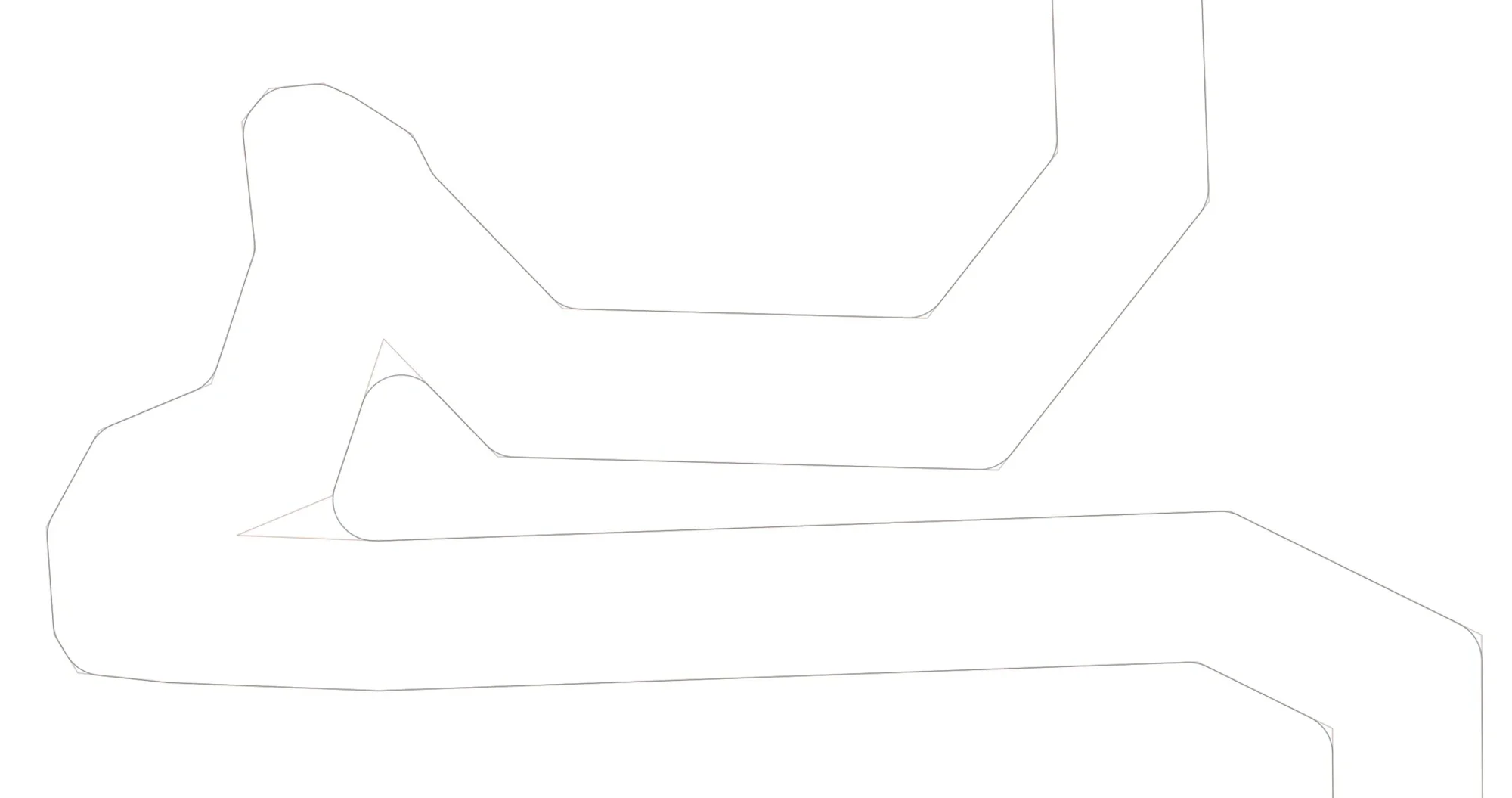
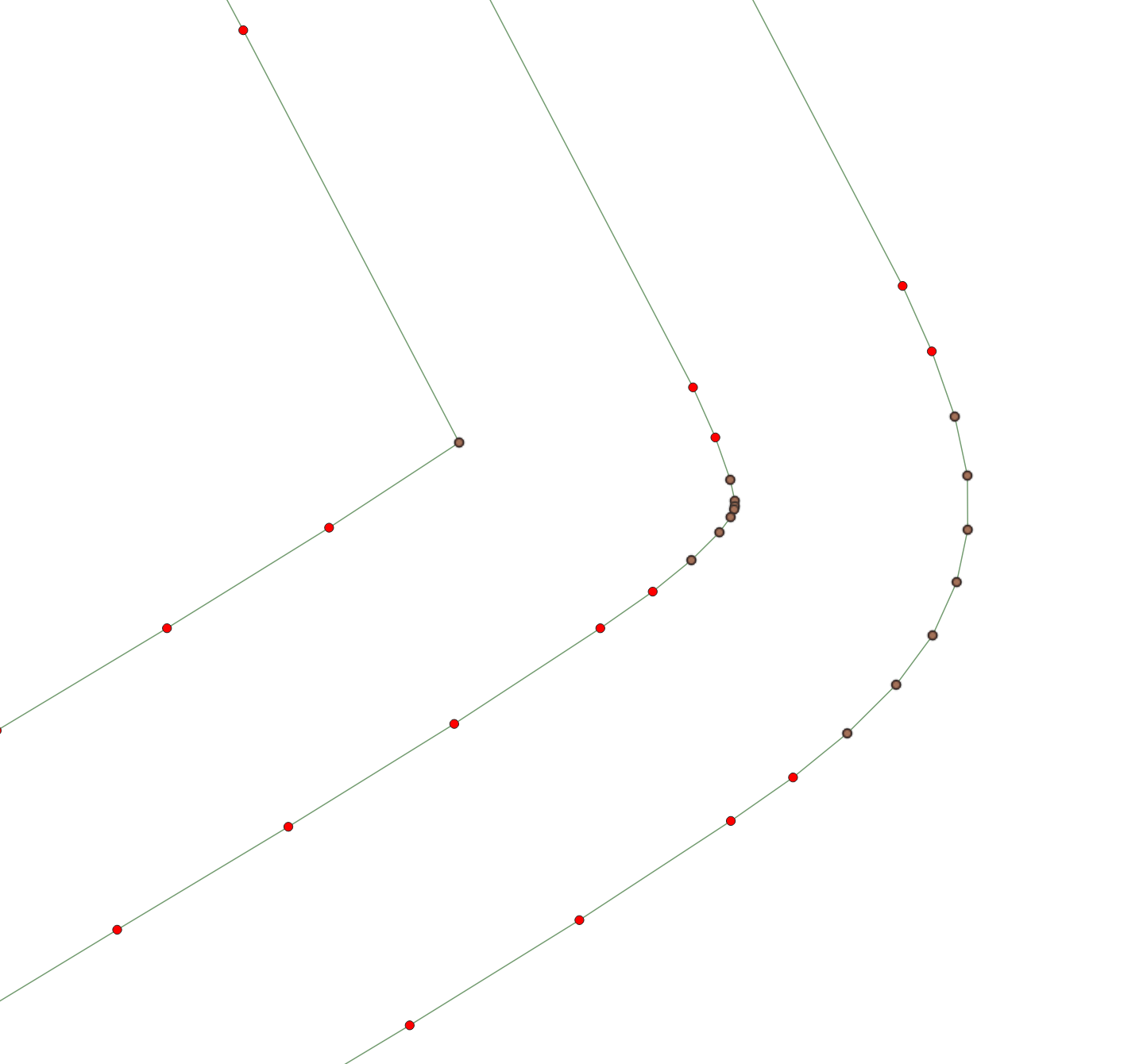
Before Smoothing
Example results of a standard offset algorithm. Brown points have angle change greater than steerable threshold
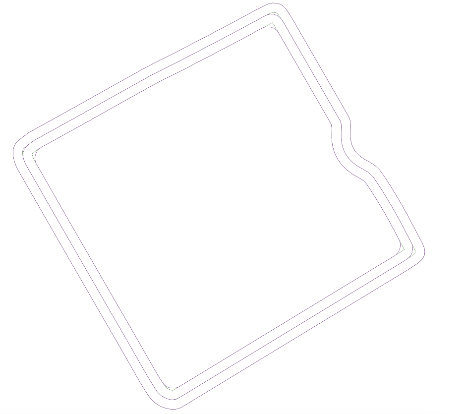
After Smoothing
After smoothing has been applied. Multiple angle violations have been combined together into one consistent smooth turn.
Headland Crosshatches
If an angle is too sharp, and the user doesn't wish to have skipped area, we can instead support crosshatches, where we extend the lines out and connect them with an arc respecting the vehicles turning radius. Realistically the below image would have only the sharpest corners as crosshatches, the rest using the above mentioned smoothing.
Trailed Implements
A vehicle may have one or more trailed implements attached behind it. We are currently modelling the main vehicle with ackermann steering geometry, with the hitch point a fixed distance behind the back axle of each vehicle + implement. Multiple implements may be chained together, and we assume all implements are non-powered. We run kinematic simulations for the vehicle traversing our turns to show where the boundaries of your equipment system will be, alerting you of any dangerous situations of leaving the field. Future work will include improving turns to account for the trailed implement, optimizing turns as to minimize stress on the hitch, any incorporating this into our search algorithm.
Grid based Representation of the Field
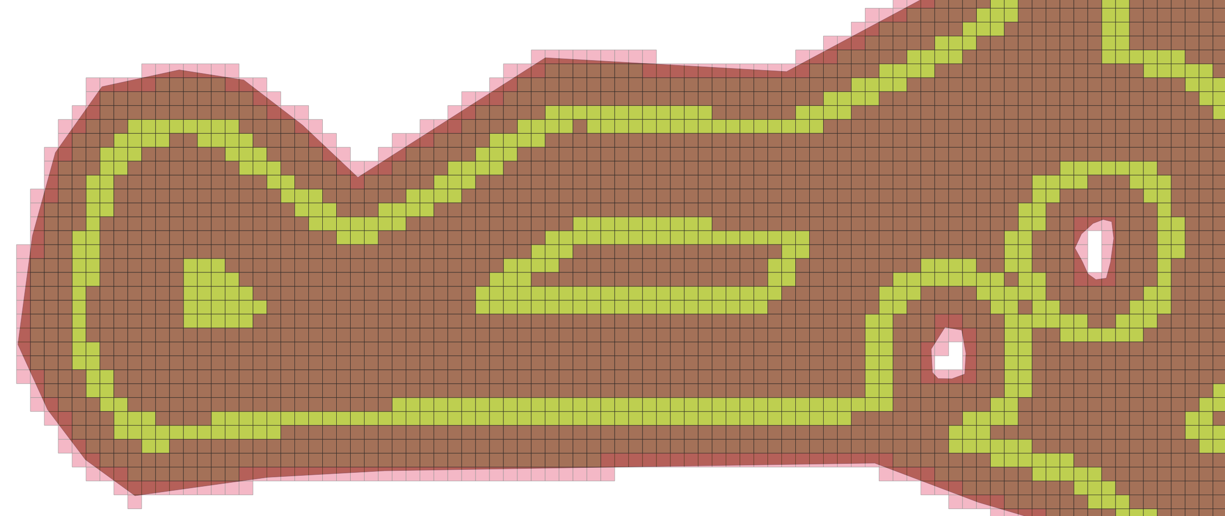
A promising approach often used in autonomy is to discretize the working area as a grid, where a type of search known as hybrid A* can be used to find the shortest steerable path between any two points on the grid. Below is an example part of a field discretized in such a manner. The green sections are headland passes and are considered preferable to travel, brown is valid headland space, and red is dangerous area that might leave the field.
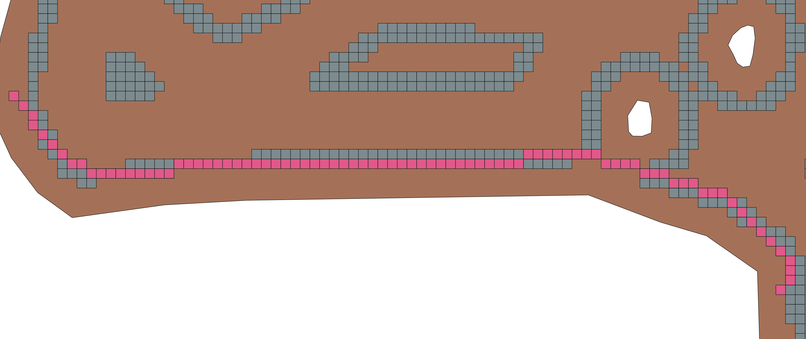
All current approaches are based on geometric methods, and thus may have difficulty finding shortcuts. An example might be the bottom section there, where a traditional approach of "always follow headland" may cause the user to needlessly drive around the obstacle, causing additional nonworking time. Running a search algorithm we can see that we may be able to drive across here. This rough estimate can help drive a finer-tuned search, validating that your vehicle along with any implements can actually make this shortcut
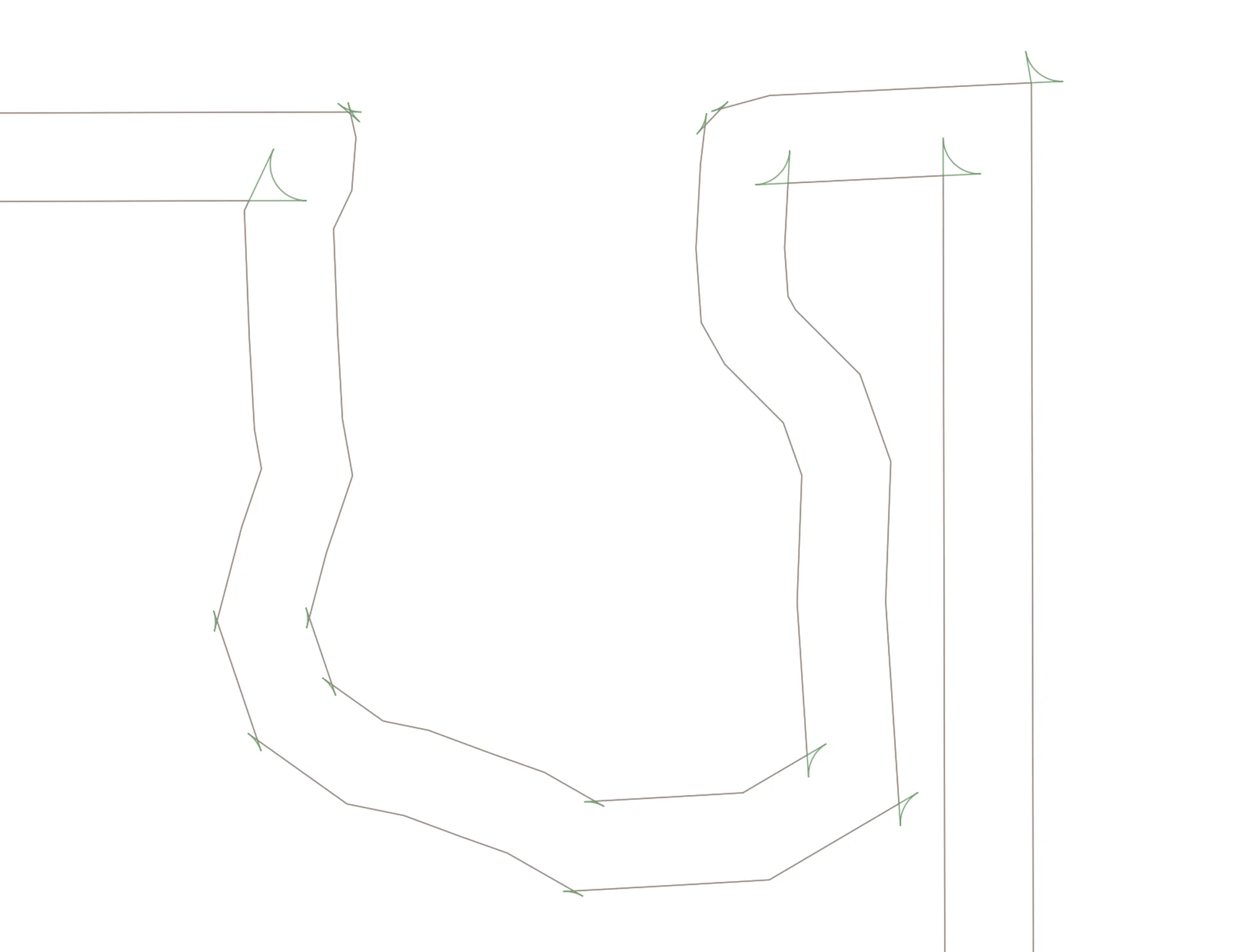
An example of a vehicle searching for a path in a simpler grid system. Notice how the planner incorporates the vehicle dimensions. The various green and brown arcs correspond to possible trajectories that the algorithm has searched through before finding the final solution. Future work includes a penalization function that avoids closely hugging walls like this video, as well as various performance improvements, preferring to traverse along headlands, and generally integrating this into our full routing solution.
More infomation coming soon about potential use cases and further examples.
Configuration Options
A list of possible options passable to the routing algorithm, as well as a brief explanation. For more information please see our API docs or reach out to us.
| Setting | Possible Values | Explanation |
|---|---|---|
Route Algoithm / Pattern
algorithm
|
Verge / Continuous Tracks / Clustered Spiral | Determines the working pattern in the field |
Problem Type
routeProblemType
|
SingleVehicle | CapacitatedMultiVehicles | What kind of routing problem we are solving, either single vehicle with no staging area, or multiple identical vehicles with staging area |
Start Point
startPointNodeIndex
|
Positive integer less than 2*trackCount | Reference to the route node index with specifies the start of the route |
End Point
endPointNodeIndex
|
Positive integer less than 2*trackCount | Reference to the route node index with specifies the end of the route |
Track Shortening
enableTrackShortening
|
true / false | Enables shortening of tracks to make headland connectors between nodes possible if it otherwise would lead to invalid trajectories (example if the turn radius is too large to make a turn onto a headland) Default: true. |
Turn Extending
enableTurnExtending
|
true / false | Enables extending of turns so that they try to touch the headland closest to the boundary. Maximum threshold to move is 1.4*swathWidth*headlandLoopCount, so in some cases may default to a closer headland. Note this will not force headland traversals, just that it touches at least one point. Default false |
Headland Drivethrough
enableHeadlandDrivethrough
|
true / false | If enabled, tracks that are on opposite sides of a headland pass and within some distance threshold will be forced as a straight connector that drives through the headland, assuming that the buffered connector doesn't intersect the boundary Default: false |
Headland Order
headlandOrder
|
OutToIn / InToOut | Determines if headlands are completed before or after interior tracks. |
headlandsFirst
Headland First
|
true / false | If enabled, exterior headland passes come first in the route. Otherwise they come after inner tracks. Default: true |
Prefer Outermost Headland
attachToOutermostHeadland
|
true / false | Forces connectors to latch onto the outermost headland when space allows. |
Prefer Shortened Headland Connections
preferShortenedHeadlands
|
true / false | Forces connectors that have to be shortened to latch onto the headland when space allows. |
Force Headland Direction
forcedDirection
|
winding / reverseWinding | The winding direction we are forced to take when connecting to a headland. Not recommended as it reduces the choices the algorithm has when picking the best path. Null implies no forced direction; however, a CCW direction is always forced for the initial exterior traversal |
Avoid Skipping Passes
preferAdjacentConnectors
|
true / false | If true, sets the cost of adjacent dubins connectors to be half of their real cost, which causes the optimizer to prefer to choose adjacent tracks, even when it may not be beneficial to for distance reasons. Default: true |
Refill Points
calculateRefillPoints
|
true / false | Determines if refill points should be calculated along a route. Only applies if doing a SingleVehicle problem. Default: false |
Refill Strategy
refillStrategyType
|
ExactPoint / StartOfTrack / NearestHeadland | Selects the refill workflow (exact node, track start, or nearest exterior headland) described in Capacity Based Routing. |