Path Planner Features
Field Boundaries
Capture and validate field boundaries from multiple sources with automatic preprocessing for optimal path planning.
Import Methods

Connected OEM FMIS
Import directly from John Deere, CNHi, and other major equipment platforms.
Shapefile/ISO Import
Upload standard GIS shapefiles from any farm management system.
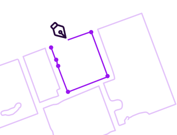
Manual Drawing
Draw boundaries directly on satellite imagery with precision tools.
Satellite Selection
Select from pre-processed global satellite imagery in seconds.
Automatic Preprocessing
- Validation: Ensures geometric integrity and removes invalid data
- Simplification: Eliminates noise and redundant points for faster processing
- Smoothing: Optimizes boundary curves for realistic machine paths
- Exclusion Zones: Define passable and non-passable obstacles (waterways, poles, nature zones)
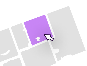
Field Decomposition
Split complex fields into optimized sub-fields to improve efficiency, reduce turns, and minimize soil loss.
Manual Decomposition
- Add points and snap lines through them
- Free-draw splitting lines
- Import external reference lines from 3rd party apps
- Automatic obstacle splitting across subfields
Automatic Decomposition
- Straight-line: Creates convex subfields to reduce turns
- Curve-based: Uses elevation contours for terraced fields
- Proprietary algorithm identifies optimal partition points
- Maximizes coverage while minimizing soil loss


Headland Management
Generate optimized headland passes with adaptive smoothing for any turning radius and regional practice.
Headland Types
Full Perimeter Passes
One or more complete loops around field boundaries and exclusion zones.
Turn-Only Headlands
Coverage only where machines actually turn, reducing unnecessary passes.
Zero Headlands
For fields with accessible roads/pathways for turning outside the boundary.
Advanced Features
- Corner Smoothing: Square or rounded corners to match any turning radius
- Point Simplification: Removes noise for cleaner, more steerable paths
- Adaptive Curves: Enables in-field execution with guidance systems
- Regional Customization: Adapts to local farming practices

Headland

Zero Headlands
Boundary Analysis
Machine learning and computer vision extract critical features from boundaries for intelligent path planning.
Straight Edges
ML identifies nearly-straight boundary segments for alignment and simplification.
Reference Curves
Computational geometry extracts long curved segments suitable for curved track planning.
Elevation Boundaries
Detects cluster contours from DEM data - natural topographical boundaries superior to single-elevation lines.
Digital Elevation Model (DEM)
Constructs 3D terrain models from public data sources or equipment telemetry. Extracts topographical features like contours and natural field divisions essential for slope-aware planning and soil erosion minimization.

Straight Track Planning
Core path planning algorithms generate parallel straight tracks optimized for coverage, efficiency, and multiple objectives.
Optimization Objectives
Primary Goals
- Maximize operational coverage area
- Minimize overlap (double coverage)
- Handle passable/non-passable obstacles
Secondary Optimization
- Minimize number of turns
- Reduce total time and distance
- Minimize point rows (headland overlap)
- Reduce soil loss potential
Alignment & Rotation
- Align to any heading (0-179° or custom decimal)
- Automatic translation for perfect edge alignment
- Rotate plans while maintaining optimal coverage
Advanced Patterns
- Guess Row: Auto-adjust spacing to reduce partial passes
- Fanning: Gradually change direction between parallel edges

Curved Track Planning
Proprietary algorithms generate curved tracks for irregular boundaries and terrain - significantly more complex than straight planning.

Reference Curve Processing
Curved tracks are generated by offsetting reference curves (boundary curves, elevation contours, or cluster contours). Pre-processing ensures curves are suitable for path planning:
- Removes winding, pinching, and self-intersecting segments
- Ensures steerability for real-world equipment
- Validates geometric feasibility
Orthogonal Projection
Projects reference curves in one or both directions by track width until field is covered. Maintains perpendicular distance equal to track width for complete coverage.
- Relaxes orthogonality when tracks pinch to maintain steerability
- Applies smoothing to each track before generating the next
- Manages vertex density to prevent over-complex paths
Dual Reference Curves
For terraced fields, reconciles two reference curves by starting with orthogonal projection of the first curve and gradually adapting to the second curve's shape. Works best when curves are slightly different.
3D Terrain Planning
Unique capability to plan in three dimensions, evaluating soil erosion potential and optimizing routes for varying elevations.
3D Terrain Modeling
Constructs 3D field models from Digital Elevation Models (DEM) sourced from public data or equipment telemetry. Rendered as rasters to extract topographical features like contours and natural field divisions.
Soil Erosion Analysis
Uses Revised Universal Soil Loss Equation (RUSLE) to measure soil loss as a function of rainfall, soil type, coverage practices, crop type, and terrain.
LS Factor (Slope-Length Factor)
Product of slope length and percentage slope - key parameter for evaluating terrain's effect on erosion.
3D Straight Tracks
Minimizes soil loss potential and optimizes uphill/downhill travel in high-slope areas.
3D Curved Tracks
More complex generation process with elegant handling of curve splitting and slope analysis to avoid floating-point errors.

Plan Analytics
Comprehensive statistics and comparison tools to evaluate route options and select the optimal plan.
Plan Summary Statistics
Line charts show summary values across field parts when fields are decomposed and planned separately.
Side-by-Side Comparison
Compare two plans visually and statistically to evaluate trade-offs. Includes simple cost comparison calculator.
- Visual overlay of different route options
- Statistical comparison of all metrics
- Cost analysis based on time, distance, and overlap
- Compare draft plans or saved plans

Export & Save
Export path plans in multiple formats compatible with all major equipment brands and guidance systems.
Export Formats
OEM-Specific Formats
- John Deere Operations Center
- CNHi (Case IH, New Holland)
- Trimble
Delivery Methods
- Direct to OEM FMIS (wireless to equipment)
- Download file for manual import
- Automatic sync with connected machines
Generic
- ISO XML
- KML
- Shapefile
File Formats
- Agres
- CNH CN1
- FendtONE
- Hexagon
- Jacto
- JD File
- Precision Planting
- Raven
- Stara
- Topcon
- Trimble
Exportable Objects
Traditional single-line guidance for basic systems
Complete track paths for advanced guidance
Perimeter passes and turn areas
Outer and inner boundaries for section control
Turns, Maneuvers, Headland connectors & Traversals
Saved Plans ("Farmer Decisions")
Filter and manage saved plans by field, operation type, and date. Take action on multiple plans simultaneously.
Collaboration
Share plans digitally with operators and team members to validate decisions and provide graphic task instructions.
Plan Sharing
Foundational collaboration feature built into the Launch Pad ecosystem from day one. Share any plan with team members for validation and feedback.
- Share with operators, agronomists, and farm managers
- Digital communication replaces verbal instructions
- Ensures everyone works from the same plan
Route-Based Task Instructions
Shared plans with routes become graphic task instructions. While exported plans guide equipment, shared plans on phones/tablets inform operators how to complete operations.
Operators can view the complete route, turn sequence, and operational context on companion devices while executing the plan in the field.

Digital Twin
Path Planner creates comprehensive digital twins of fields by layering geometric, physical, and operational data.
Seven-Layer Digital Twin
-
1Full Route Layer
Complete end-to-end machine trajectory with turns
-
2Path Plan Layer
Optimized equipment movement paths
-
3Coverage Layer
Full implement coverage with minimized overlap
-
4Slope Layer
Slope optimization for equipment and erosion control
-
5Decomposition Layer
Sub-field partitions for operational efficiency
-
6Topography Layer
3D terrain representation with elevation data
-
7Field Geometry Layer
Boundary characteristics and shape analysis

Farm-Level Aggregation
Individual field digital twins aggregate into a comprehensive farm digital twin. This enables farm-wide land management optimization, equipment fleet design, and operational planning across all fields and operations.
Full Route Generation
Complete end-to-end routes including paths, turns, sequencing, and start/end point connections - essential for autonomous systems.
Comprehensive Routing Capabilities
Our state-of-the-art routing solution supports arbitrarily complex fields with sophisticated turn modeling, headland navigation, and intelligent path optimization.
- Smart Turn Modeling: Automatically selects optimal turn types (U-turns, bulb turns, P-turns) based on field geometry and equipment characteristics.
- Advanced Headland Navigation: Enables efficient traversal between field areas with configurable options for headland-first or headland-last patterns, outermost headland preference, and full headland traversals around complex obstacles.
- Proprietary Routing Algorithm: Calculates distances between all track pairs to create an optimized path that minimizes non-working distance while handling irregular fields, exclusion zones, and multiple obstacles.
- Capacity-Based Routing: Plan refill points and optimize routes based on vehicle capacity and flow rate. Single vehicle workflows support exact refill points, start-of-track positioning, or closest exterior headland placement. Multi-vehicle staging area routing (CVRP) optimizes fleet operations with vehicles returning to staging depots when capacity is reached.
- Additional Capabilities: Experimental features like steerable smoothing and trailed implement support, plus extensive configuration options to match your operational preferences.
See It In Action
Explore detailed examples, visual demonstrations, and in-depth explanations of all routing capabilities
Explore the Complete Routing Showcase